Building a Pixel-Scan Camera From Scratch
A while ago I came across this project, where two designers construct a rudimentary camera by stacking thousands of drinking straws in front of a photosensitive film. Each “pixel” sees only the light that passes the length of its associated straw, so images can be formed as long as the subject is within some characteristic distance of the camera determined by the length and width of the straws. I think this project is fascinating because the camera captures images in perpendicular projection, rather than perspective projection; since each pixel sees only the light rays incident on it at 90 degrees, the camera has no focal point.
I was thinking about ways of applying the same concepts to a digital camera, and it occurred to me that, rather than wire up a system of thousands of photodiodes, each potted into a dedicated straw, it would be interesting to capture a single pixel at a time by physically scanning a single straw across the scene. This would open up a lot of possibilities - the straw could be translated to get a perpendicular projection, rotated to get a perspective projection, or moved through any combination of the two techniques. Going beyond 2-dimensional projections, the camera could capture a full light field, or information about the light incident on every point in a plane from different angles.
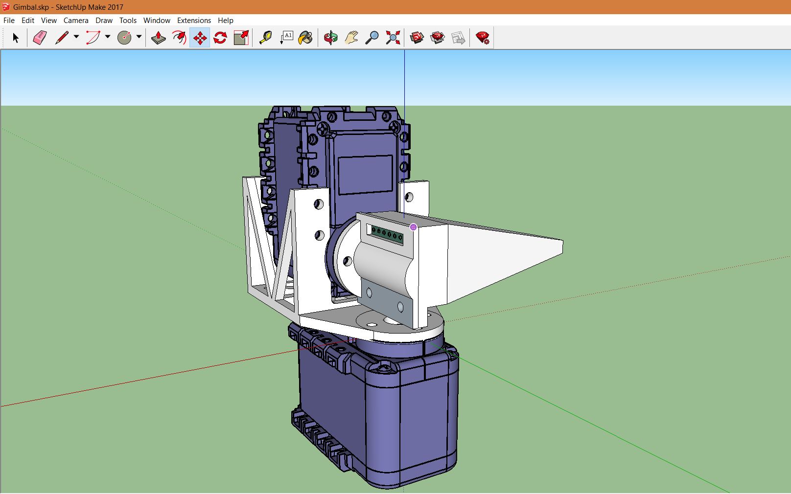
I have built 2- and 3-axis rotating gimbals before using cheap hobby servos, and while they’ve worked well, I knew the “slop” in the rotational accuracy of a plastic-geared hobby servo would limit my resolution for this project. After a bit of research, I splurged and bought two Dynamixel AX-12A robotic servos. I used Sketchup to CAD a gimbal and mount system for the photodiode:

This was my first time using Sketchup - in the past I have used the Autodesk suite, since it’s free for students. I definitely missed the parametric properties of Autodesk, and I think I would have missed them more if this project’s CAD had needed any significant revision, but Sketchup got the job done in the end.
Electronically, the system is pretty simple. I used a 9V battery to drive the dynamixel servos, and put together a small interconnect board to connect the necessary control pins from the servos and photodiode to an Arduino. The servos can be a bit of a current load; in the gimbal configuration they draw about 50 mA of current at rest, more if the wire harnesses are particularly stiff or exert any significant stress on the gimbal. At some point, I may try to look at whether this resting current can be reduced by tuning the servo PID parameters. It seems like a little bit of overshoot could go a long way towards transferring the mechanical stress onto the static friction in the system, rather than the motor coils themselves. As it is, if I’m not careful with the wires it’s easy to burn through a whole 9V battery during a single 90 minute exposure.
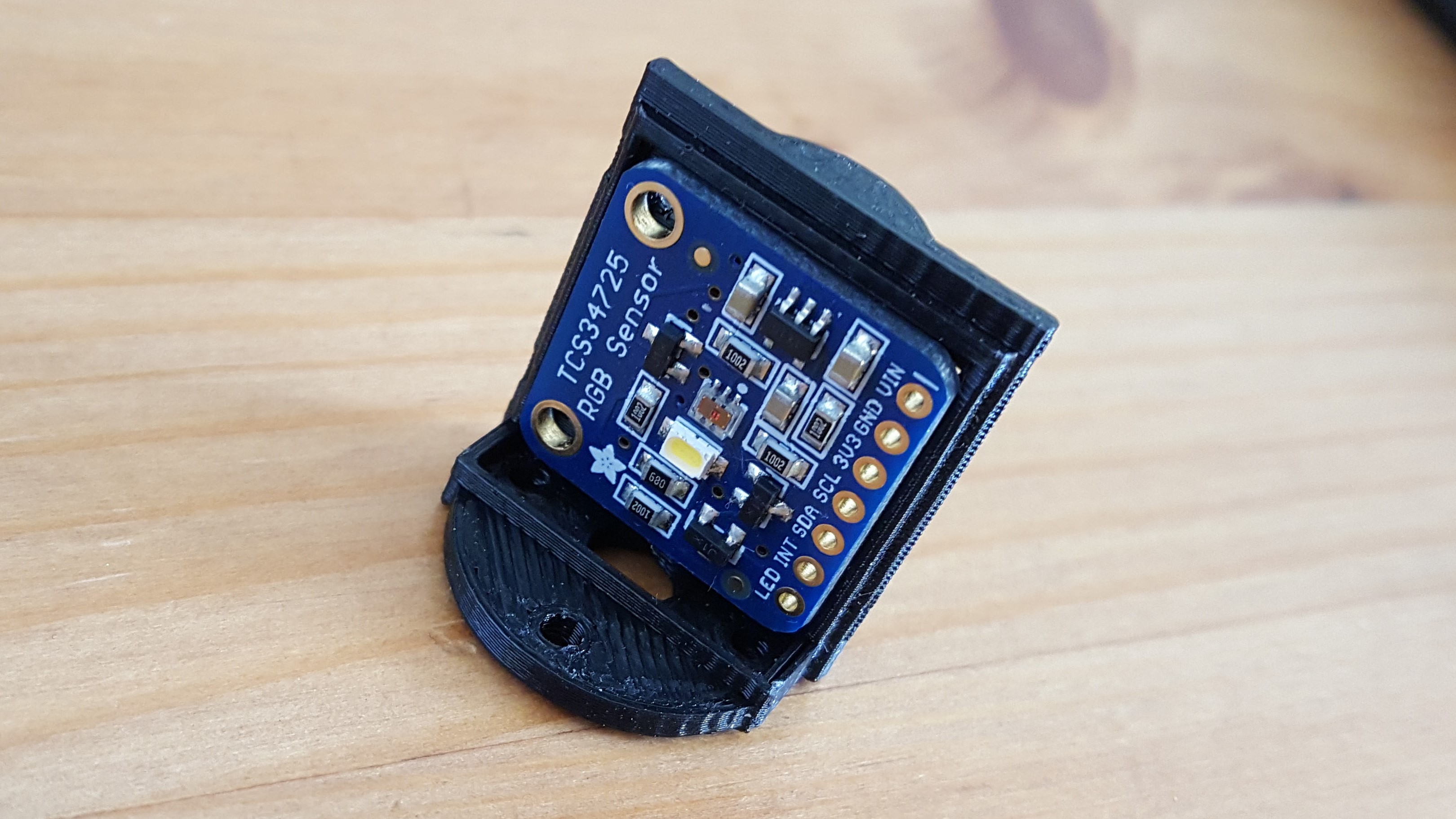
For the photodiode, I selected a TCS34725 with an Adafruit interface board. It speaks in I2C, and the servos have their own 1-wire serial protocol. I found Arduino libraries available online for both, although I never got great performance from the dynamixel library. it took some modification to get going, and there are several features that aren’t working for me yet. As it is, I’m currently using single-motor commands to address the two servos individually. This works well enough, but I’d like to eventually move to the two-motor commands supported by the AX12A, so that both motors move simultaneously (currently, I wait for the yaw motor to move before moving the pitch motor). It takes about 1.2 seconds per pixel to capture an image with my current setup. 700ms of that is the photodiode integration time, and 500ms is for the motors to move.

The least-controlled aspect of the system today is the pinhole diameter. I initially tried poking a hole in electrical tape for the pinhole, but found that the tape was so elastic that the hole closed within an hour or two. Currently I’m using three layers of blue painter’s tape with black sharpie to increase the opacity. I estimate the pinhole is about a millimeter in diameter, which provides remarkably good spatial resolution; below 1mm, the limiting factor in the system resolution actually becomes the area of the photodiode surface, rather than the pinhole. If I capture an image in full daylight with the highest gain and longest exposure settings, I can get a dynamic range from the photodiode of about 0-1000. I had some issues with ambient light leaking into the photodiode enclosure through the seams, so for my first few images I’ve been using the same tape to provide a better optic seal.

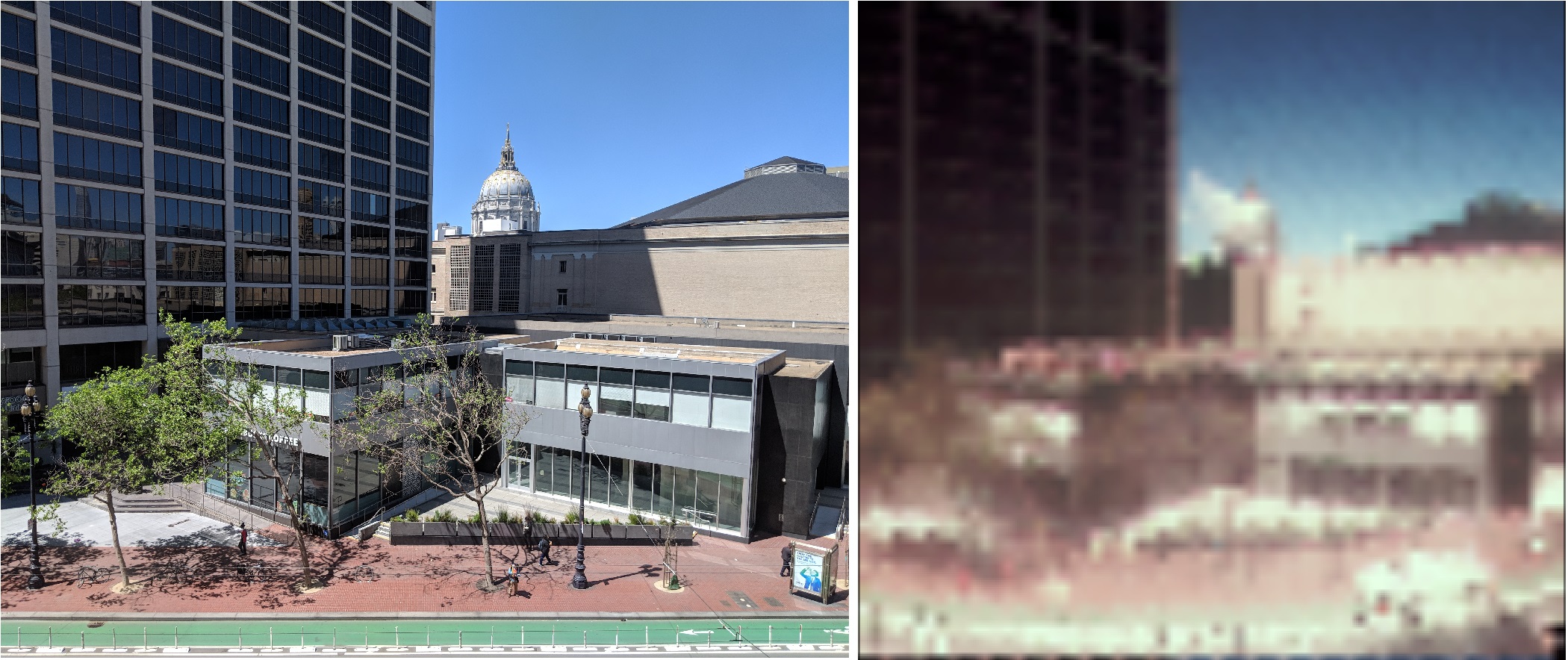
After the pixels for an image are captured, I use a naive histogram adjustment to improve contrast, based on this algorithm. I’m still fine-tuning the postprocessing (the green channel in particular looks washed out), but I’m more or less happy with the images I’m getting today. Below, you can see a side-by-side comparison of a scene captured with my cellphone camera and the pixel-scan camera. I’ve lightly blurred the pixel-scan image during the up-sampling process; the original resolution is 64x64, at about 0.9 degrees of rotation per pixel.

Interestingly, the resolution of the 64x64 image doesn’t seem to hit the floor of what the pinhole can do; you can see that some of the white columns on the building to the left are aliased out of the image, indicating that the spatial resolution of the pinhole is greater than the 0.9 degree sampling angle. I’ll keep playing with this and the other parameters of the system. Meanwhile, you can view the project github page here.